| A controlled gas filled metal-ceramic spark gaps RGU type are assigned for voltage and current switching during high voltage pulse testing, in electrotechnology (magnetic punching, stone crushing), in laser equipment etc. Spark gaps can operate in vertical and horizontal position. The spark gaps operate under pressure of air up to 3,0 kgc/sq. sm with a purge or without a purge of volume.
LIMITING CLIMATIC INFLUENCES
Rating values of climatic factors in accordance with ГОСТ 15543-70 and ГОСТ 15150-69. Values of operating temperature are in a range + 1 ? + 35°С. Height above sea level no more than 1000 m.
An environment is not explosive, not containing a current-carrying dust and aggressive gases in the concentration lessening parameters of a spark gap to non acceptable limits.
LIMITING MECHANICAL INFLUENCES
The spark gap maintain influence of vibrating loadings in a range of frequencies 5 ? 200 Hz with amplitude of 0,5 mm, acceleration 19,6 m/s2 and influence of shock loadings with acceleration 147 m/s2 and duration of impact 5 ? 10 mс.
CONSTRUCTION OF A SPARK GAP
A typical design of a spark gap is shown in figure 17.
Fig. 17. Cross-section of a spark gap with the electric circuit of connection:
1,7 - flanges of electrodes; 2,8 - fixing flanges; 3 - an electrode of control; 4 - a disk with an aperture;
5,6 - the basic electrodes; Rн - resistance of loading;R1,R2- resistance of a divider of a voltage;
С1 - separating capacitance; Тр- the high-voltage transformer, Uр - a operating voltage
charging devices.
The spark gap has three electrodes 5, 6 and 3, one of which is the electrode of control or starting 3 is located on equipotential surface between identical basic electrodes 5 and 6. The starting electrode, represents a flange with a round plate in its center there is an hole with a sharpened edge. The starting electrode is set equally spaced from the basic electrode and has potential equal to half of operating voltage which is supported by a high-voltage ohmic divider. At submission of a high-voltage pulse of control on a starting electrode the gas interval between a starting and basic electrode is broken into. After that all operating voltage appears enclosed to other interval, that also causes its breakdown and short circuit of a spark gap.
For the increasing of a design life the case of a spark gap is made of high-strength cermet. Copper is used as the material for basic electrodes and a starting electrode. If it is necessary to increase the a service life of a spark gap instead of copper the alloy of copper the alloys of copper with vanadium or copper with tungsten can be used. The control pulse gets on a starting electrode through separating capacitor C1. The starting pulse is usually formed with the help of pulse transformer Tp though other circuits of start are possible also.
The basic advantages of the given spark gap are:
1. The high mechanical durability providing its reliable operate at the big currents up to 100 kA without damages of the case during all service life;
2. An opportunity of easy replacement of worn elements of a spark gap, namely concerning cheap electrodes 4, 5, 6 with the purpose of prolongation of service life twice and more;
3. An opportunity of operate without reorganization of pressure in a range (0,2 - 1,0) х Uop., at use of the control of device of the manufacturer (the specified property is important for some applications, for example, at use of a spark gap in the circuit "krow-bar").
4. High stability of a voltage of self-breakdown of the spark gap, connected to the absence of significant influence of the gas discharge on ceramic walls of a spark gap and as consequence the stability of operation a working regime.
Three types of the spark gap differing in diameter of a ceramic cylinder and a limiting current of the discharge are developed: RGU-1, the having diameter O of 125 mm and a limiting current 100 kA, RGU-2 with diameter O 80mm and a current 50 kA and RGY-3 with diameter O 25 mm and a current 20 kA.
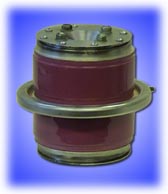
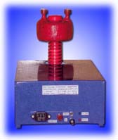
The External view of spark gap is shown in figure 18.
A spark gaps has am operating voltage from 1 up to 100 kV and the maximal operating current from 20 up to 100 kA. Characteristics of spark gap are given in table 7.
The range of operating voltage given in the table, is specified at constant pressure of 760 mm of a hg, t = 20 0C and using a control device of the Manufacturer. The range of the minimal voltage of operation of a spark gap is specified with accuracy ±15 %. With the application of control device of a usual design the minimal working voltage increases up to 0,5Uop. The value of a current shown in the table, corresponds to the maximal peak value of a current. The maximal charge is specified for a case of duration of a pulse current less then 100 ?s. At longer pulses the maximal charge should be significantly reduced. The design life given in the table, also is specified for cases of duration of a current less than 100 ?s. At such duration first fails the starting electrode and only then comes a big deterioration of the basic electrodes. On our data deterioration of a starting electrode equal 1,1·10-4 g/K, and the basic electrodes equal 4,4·10-5 g/K, that is in 2,5 times less. At duration a pulse of a current more than 100 ?s the design life can be significantly lower. For example, spark gap RGU 1-30-100 in our researches has broken down at a design life 6,2·103 K, a charge transferable for a pulse 1,44 K and duration of a pulse of a current 700 ?s.
The limited frequency of operation of a spark gap is specified for a case of operation of a spark gap at atmospheric pressure, without a purge and the rated voltage close to self-breakdown. At operation with a lower operating voltage limited frequency of operation of a spark gap increase, as we can see from figure 19. It is necessary to note also, that big heating of a spark gap reduces a voltage of self-breakdown and consequently reduces limiting frequency. The weight of a spark gap is specified without a control system with accuracy of 20 %.
Recommendations on installation and operation
During installation of a spark gap it is necessary to avoid sharp corners in places of fastening current trunks. The spark gap can operate both in vertical, and in horizontal positions.
For a purge of a spark gap dry air should be used. Because of the presence of a high pressure of a condensate water in a gas systems, it is necessary to use filters, to avoid moisture getting into operating volume of a spark gap.
Before operation the spark gap should be tested by 100/200 discharges at a usual voltage.
The spark gap should be supplied with two resistance leveling a voltage, equal 400/600 MOm (a divider of a voltage) which are put between the anode, control an electrode and the cathode.
The setting control pulse is sent to a control electrode through high-voltage capacity equal 500-1000 pF and a rate voltage.
The service life of a spark gap is limited to deterioration of control electrode. It is possible to prolong service life of a spark gap twice as much by replacement of the worn out control electrode, which represents a thin (2 mm) copper ring with the central hole, and in case of need replacements of the demountable cathode and the anode of a spark gap.
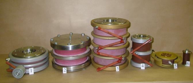
Fig. 18. Appearance of cermet gas spark gaps RGU type:
1 – RGU 1-15-100 (15kV, 100kA ); 2 - RGU 1-50-100 (50kV, 100 kA);
3 - RGU 1-100-100 (100kV, 100 kA); 4 - RGU 2-50-50 (50kV, 50 kA);
5 - RGU 2-10-50 (10kV, 50 kA); 6 - RGU 3-20-20 (20kV, 20 kA).
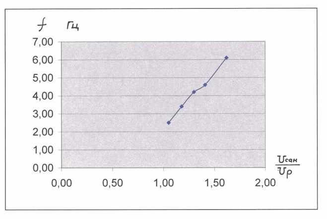
Fig. 19.Dependence of the maximal frequency of operation of a spark gap from parameter Uсам/Uр;
Uсам -a voltage of self-breakdown;Uр- a operating voltage of a spark gap; without a purge;
experimental dependence is expressed by the formulaf = 7,1 х(Uсам/Uр)- 5 |